
 Buy Now
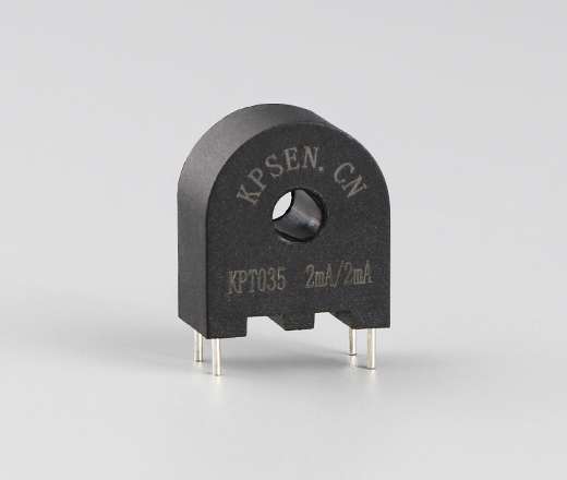
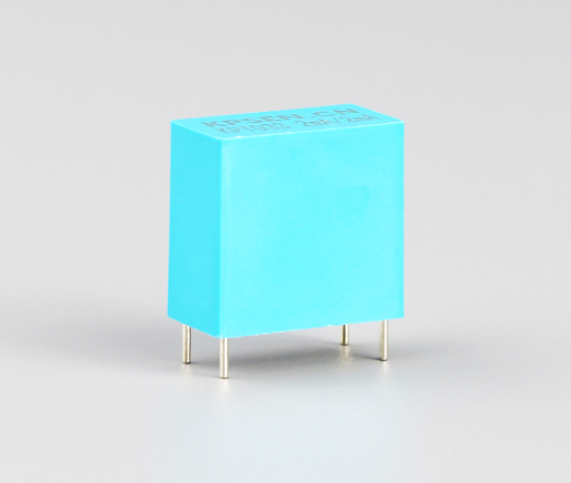
Input current: 2mA; Output current: 2mA; Current ratio: 1000:1000
It is suitable for converting high voltage signal into low current signal proportional to it, which is easy to measure and protect the use of equipment.
Passed ISO 9001:2015; Fully compliant with RoHS and REACH requirements


Nanocrystalline magnetic core (high precision, good linearity)
Epoxy potting, safe and reliable;
Flame retardant (according to UL94-V0);
Environmental protection (compliant with EU RoHS and REACH standards)
Small size, light weight, easy to assemble and weld.

Detecting overload current
Ground fault detection
Measure
Analog to digital circuits

Operating environment: temperature -40℃~ +85℃,
Storage environment: temperature -40℃~ +85℃,
Relative humidity: not more than 95%(25℃)
Reference standard: IEC 60044-1&GB&T 20840.1-2017&ANSI C57.13
ELECTRICAL PROPERTIES(at 25°C) | |||||||||
Model number | Input current | Output current | Turn ratio | Linear range | Phase difference | Precision | Load resistance | Withstand voltage | Operating frequency |
KPT035 | 2mA | 2mA | 1000:1000 | 5~120% | ≤30’ | 0.2 | ≤20Ω | 3000V | 50Hz~60Hz |
KPT035 | 2mA | 2mA | 1000:1000 | 5~120% | ≤30’ | 0.2 | ≤20Ω | 4000V | 50Hz~60Hz |
KCT104P/2 | 5A | 5mA | 1000:1 | 5~120% | ≤30’ | 0.2 | ≤20Ω | 3000V | 50Hz~60Hz |
Note: 1, pay attention to the load connected to the transformer secondary, exceeding the rated load capacity may lead to Precision reduction or saturation.
2, if the above table is not suitable for your use of products, we can according to your technical and structural requirements tailored to your products.

Size unit: (mm)
Dimensional tolerance: ±0.5mm(unless otherwise specified), foot distance tolerance: ±0.3mm
Note: Terminal resistors and one-turn primary are not provided unless requested
.png")
Note: The principle diagram shows the basic working principle of the transformer. The sampling circuit of the transformer can be customized.

As shown in the figure above: Parallel resistor R directly outputs the circuit. When the voltage transformer works at rated current 2mA, the resistance R is not more than 300Ω(output maximum saturation voltage 1V), and the secondary load is R. The direct output circuit is larger due to the load phase difference, but the linearity is basically unchanged, which is still better than 0.1%. Suitable for low-demand occasions. Figure 1 C can play a certain phase compensation role, no phase requirements can not be added. Compensation amount: △δ=-100πCR*3438 ', this circuit should be selected as the load R precision transformer. If the actual error of 0 load precision transformer is still offset in the negative direction, the linearity is basically unchanged.

We are a service provider that can provide a complete set of electronic component technology. Specializing in the production, research and development, and sales services of amorphous nanocrystalline iron cores, transformers, and sensors.


If you have any questions or need assistance, please feel free to contact our team at any time.
Building 4A, Huiye Science and Technology Park, Fenghuang Street, Guangming District, Shenzhen


 EN
EN
 CN
CN